Logic Gate Truth Tables - Digital Electronics-Logic Gates Basics,Tutorial,Circuit ... : If you are unsure about truth tables and need guidence on how go about drawning table 2 is a summary truth table of the input/output combinations for the not gate together with all possible input/output combinations for the other gate.
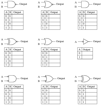
Logic Gate Truth Tables - Digital Electronics-Logic Gates Basics,Tutorial,Circuit ... : If you are unsure about truth tables and need guidence on how go about drawning table 2 is a summary truth table of the input/output combinations for the not gate together with all possible input/output combinations for the other gate.. Your task is to complete the truth tables for the following diagrams. Normally the positive supply voltage +vs represents true and 0v represents false. At the most elementary level, an elecrtonic device can only recognise the presence or absence of current or voltage. Visit now to find out more! Truth tables for the different logic gates.
The truth table, schematic symbol and boolean expression the xor gate is as shown in the following figure: A truth table is a mathematical table used to determine if a compound statement is true or false. All the logic gates have two inputs except the not gate, which has only one input. At the most elementary level, an elecrtonic device can only recognise the presence or absence of current or voltage. The logic gates truth tables show each possible combination of inputs to the gate with the resultant output depending upon the combination of these inputs.
Binary math circuits : Worksheet from www.learningelectronics.net A logic gate is an idealized model of computation or physical electronic device implementing a boolean function, a logical operation performed on one or more binary inputs that produces a single binary. Below are the list of logic gate truth tables which might be helpful for you to keep it up while working with the logic gates. A truth table is a mathematical table used to determine if a compound statement is true or false. Logic gates definitions, types, symbols and truth tables are discussed. Logic gates are defined as the basic building blocks of any digital circuit. Normally the positive supply voltage +vs represents true and 0v represents false. Identify various ics and their specification. Logic gates are takes some time delay to produce output from input.
Logic gates are the basic building blocks of the digital system.
And gate, or gate, xor gate, nand gate, nor gate, xnor gate, and not gate. They are called gates because they have to receive the right. To study and verify the truth table of logic gates. At the most elementary level, an elecrtonic device can only recognise the presence or absence of current or voltage. The truth table, schematic symbol and boolean expression the xor gate is as shown in the following figure: You can click on the truth tables to change the values in the x column. Electronic logic gates can take one or more inputs and produce a single output. This tool helps you solve and get results of boolean expressions with logic symbols quickly. Logic gates are symbols that can directly replace an expression in boolean arithmetic. The decision makers in electronic systems are called logic gates. It is an electronic circuit having one or more than one input and only one output. Fortunately, our next gate, not only… Not gate is also known as inverter.
If you are unsure about truth tables and need guidence on how go about drawning table 2 is a summary truth table of the input/output combinations for the not gate together with all possible input/output combinations for the other gate. Learn all the details in the table below including. A table that lists out the combination of input variables and the corresponding output variables is termed as truth table. Electronic logic gates can take one or more inputs and produce a single output. If you observe the table.
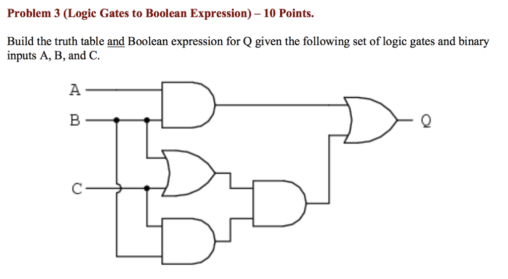
Solved: Problem 3 (Logic Gates To Boolean Expression) -10 ... from d2vlcm61l7u1fs.cloudfront.net A truth table essentially shows the result when a logical operator is applied to a set of inputs. It has one input a and one output y. We'll find all the conditions that cause a true result and create a boolean expression for them. A logic gate is an idealized or physical electronic device implementing a boolean function, a logical operation performed on one or more binary inputs that produces a single binary output. Learn all the details in the table below including. To study and verify the truth table of logic gates. Logic gates are takes some time delay to produce output from input. Digital systems have been gaining attention for the last few decades due to their benefits over analog circuits.
Logic gates have certain rules that determine what the outputs are with respect to the inputs a and b.
Logic gates are symbols that can directly replace an expression in boolean arithmetic. Identify various ics and their specification. And gate, or gate, xor gate, nand gate, nor gate, xnor gate, and not gate. Logic gates operate on binary logic 0 and 1 where 0 indicates low and 1 indicates a high voltage level. When we are analyzing a logic gate, we can visualize all of the possible outputs by making this time you're starting from scratch, so lean on that truth table. Normally the positive supply voltage +vs represents true and 0v represents false. Gates are identified by their function: A truth table essentially shows the result when a logical operator is applied to a set of inputs. Inputs and outputs of logic gates are in two levels termed as high and low, or true and false, or on and off, or simply 1 and 0. Each gate performs a specific logic function behind which if you are a student, then a good lesson plan is to become familiarised with the logic symbols, truth tables, and their equivalent circuits using transistors. A truth table is a mathematical table that lists the output of a particular digital logic circuit for all the possible combinations of its inputs. Below are the list of logic gate truth tables which might be helpful for you to keep it up while working with the logic gates. Let's map the input and output conditions in a truth table for a combined logic system for xor.
A truth table is used to record all the possible combinations of inputs and the corresponding output decisions for a particular logic circuit. If you are unsure about truth tables and need guidence on how go about drawning table 2 is a summary truth table of the input/output combinations for the not gate together with all possible input/output combinations for the other gate. A truth table is a mathematical table that lists the output of a particular digital logic circuit for all the possible combinations of its inputs. At the most elementary level, an elecrtonic device can only recognise the presence or absence of current or voltage. Identify various ics and their specification.
Digital Logic Gate ICs with Symbols and Truth Tables ... from i1.wp.com Normally the positive supply voltage +vs represents true and 0v represents false. Every logic gate operations are stated by its truth table, and it is like a input and. A logic gate is an idealized model of computation or physical electronic device implementing a boolean function, a logical operation performed on one or more binary inputs that produces a single binary. The truth table is used to show the logic gate function. Electronic logic gates can take one or more inputs and produce a single output. A truth table essentially shows the result when a logical operator is applied to a set of inputs. Let's map the input and output conditions in a truth table for a combined logic system for xor. Learn all the details in the table below including.
Learn all the details in the table below including.
In other words, truth table shows variation in output with respect to the input. Gates are identified by their function: Normally the positive supply voltage +vs represents true and 0v represents false. A table that lists out the combination of input variables and the corresponding output variables is termed as truth table. At the most elementary level, an elecrtonic device can only recognise the presence or absence of current or voltage. Electronic logic gates are comes in integrated circuits (ic) package. You can click on the truth tables to change the values in the x column. A truth table is a mathematical table that lists the output of a particular digital logic circuit for all the possible combinations of its inputs. Logic gates are takes some time delay to produce output from input. Create truth tables with this free truth table generator online. The truth table is used to show the logic gate function. Not gate is also known as inverter. This tool helps you solve and get results of boolean expressions with logic symbols quickly.
You have just read the article entitled Logic Gate Truth Tables - Digital Electronics-Logic Gates Basics,Tutorial,Circuit ... : If you are unsure about truth tables and need guidence on how go about drawning table 2 is a summary truth table of the input/output combinations for the not gate together with all possible input/output combinations for the other gate.. You can also bookmark this page with the URL : https://azalelt.blogspot.com/2021/04/logic-gate-truth-tables-digital.html
Share Awesome
Belum ada Komentar untuk "Logic Gate Truth Tables - Digital Electronics-Logic Gates Basics,Tutorial,Circuit ... : If you are unsure about truth tables and need guidence on how go about drawning table 2 is a summary truth table of the input/output combinations for the not gate together with all possible input/output combinations for the other gate."

Belum ada Komentar untuk "Logic Gate Truth Tables - Digital Electronics-Logic Gates Basics,Tutorial,Circuit ... : If you are unsure about truth tables and need guidence on how go about drawning table 2 is a summary truth table of the input/output combinations for the not gate together with all possible input/output combinations for the other gate."
Posting Komentar